Global Safe Torque Off (Strings 2 or 3)
General information (global STO)
|
|
The global STO function uses the following devices: MKD-C, AKD-N without option "DS" or "DT", Kollmorgen hybrid connection string cable. |

There is one STO input and one STO-Status output for every DC Power string.
The string STO input release the power output stage of all AKD-N (without option DS/DT) connected to the string as long as a 24 V signal is applied to this input. If the STO-Enable goes open-circuit, then power will no longer be supplied to the connected motors, and the drives will lose all torque and coast to a stop.
|
|
In case of using AKD-N with option "DS" or "DT" (local STO input), the global STO signal will have no influence to these specific drives. |
|
|
In case of using more than 8 AKD-N with Hardware Revison A or B in one string, you must connect a signal buffer to the STO signal.
|
Technical data and connection (global STO)
|
|
The global STO inputs are not compatible with IEC 61131-2. Connector X16 ensures requirements of pollution level 3 according to IEC 60664-1. |
|
STO String X inputs |
|
|
STO-Status outputs |
|
|
STO 24 VDC supply |
|
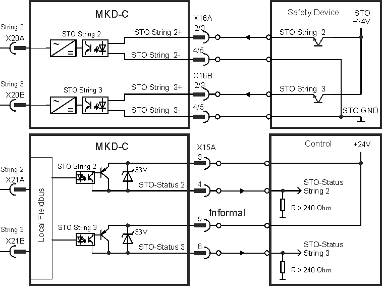
Pinout connector STO signals
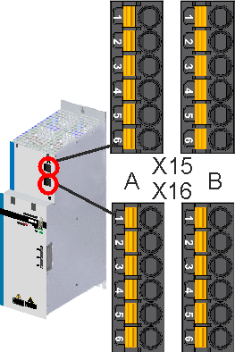
|
|
Wiring diagram STO Signals, example
Environment notes and wiring requirements: Enclosure, wiring.
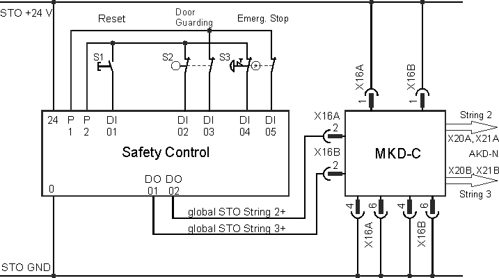
Application example (global STO)
The sample application below shows door guarding and emergency stop, controlled by a safety control to switch the global STO inputs of an MKD-C device to SIL2, PLd. Both drive strings are switched independently.
|
|
Kollmorgen KSM modules cannot be used. |
Functional description (global STO)
There is one STO input and one STO-Status output for each string. The string STO input releases the power output stage of all AKD-N (without option "DS" or "DT") connected to the string as long as a 24 VDC signal is applied to this input. When STO function is engaged during operation by separating STO from 24 V, the drives (without option DS/DT) connected to the string slow down without control.
When the global STO function (Safe Torque Off) is not needed, then the inputs STO inputs must be connected directly to +24 VDC. The function is then bypassed and cannot be used in the machinery safety concept.
Possible states of the drives connected to the string referring to the global STO function:
|
String |
String |
String |
Safety acc. to SIL2 |
AKD-N on the String can produce Torque |
|---|---|---|---|---|
|
0 V |
no |
high |
yes |
no |
|
0 V |
yes |
high |
yes |
no |
|
+24 V |
no |
low |
no |
no |
|
+24 V |
yes |
low |
no |
yes |
|
|
Use the following functional sequence when the STO function is used:
|
|
|
It is not possible to perform a controlled brake if the STO is off. If controlled braking prior to the use of the STO function is necessary, the drive must be braked first and the STO input must be separated from +24 V time-delayed. |
|
|
When wiring the STO circuits within a enclosure, the cables and the enclosure must meet the requirements of IEC 60204-1. If you are wiring leads outside the specified enclosure, then the cables must be laid durably and protected from outside damage. Use Kollmorgen cables only. |

Functional test (global STO)
|
|
You must test the safe torque off function after initial start of the drive, after each interference into the wiring of the drive, or after exchange of one or several components of the drive. |
First Method:
- Stop drives in the string with setpoint 0 V. Keep drives enabled.
DANGER: Do not enter hazardous area! - Activate the global STO function for example by opening protective screen of the string, where the drives are connected (voltage at STO input = 0V).
- The MKD-C fault contact opens, the corresponding string STO-Status message changes the voltage level, the drives lose torque and slow down to zero speed without control.
Second Method:
- Stop all drives in the string with setpoint 0 V, disable the string.
- Activate the global STO function, for example, by opening protective screen (voltage at STO input = 0V).
- The corresponding string STO-Status message changes the voltage level, the string cannot be enabled.